Sunday, October 30, 2011

Welding captive nuts and filling holes on the frame

The rear subframe had a few holes drilled in it for unknown reasons (but probably alarm related) by previous owners. I decided I disliked them sufficiently that I should try filling them with weld. 

There was a large diameter (c. 13mm) hole in a cross-brace with the VIN plate and a small hole next to it, probably for a self-tapping screw. I scraped off the sticker then ground the rust from the hole perimeter with a mini grinder. 


 Next came the MIG work. It went pretty well, carefully adding bead to bead with enough time to cool between each burst to stop the whole thing from dropping through. It only needed a few seconds between each bead for this. Finally, a flap wheel on an angle grinder restored the level of the material. There are a couple of little imperfections in the surface but rather than risk sorting them with more weld, I decided they'd fill with primer easily enough. 


The other welding I needed to do was to restore six captive nuts that had split away from the frame. Three were M8s for the exhaust mounting brackets, two M8s for the grab rail and rear fairing panels, one was an M8 for the left-hand rear indicator bracket, and one M6 for the right-hand rear fairing panel. The mini-grinder came out again to get enough shiny metal for me to weld to. This was very tricky as it turned out because of restricted access to all but the M6. In each case, I wound a bolt tight into the nut to ensure there was good electrical contact, then welded some wire into the frame near it, running up to the nut itself.


A captive nut - that's captive again!
Rear subframe after all welding
and grinding was complete.
Finally, I used a wire brush on a drill to bring all the rust off where it had developed. In most cases, these places were on factory frame welds, in the others it was nicks and scratches. I finished up with zinc primer, pending rubbing back on main spar sections and a coat of black.

Rear subframe after derusting and priming

Tuesday, October 18, 2011

When the Trophy 1200 hit the roads in 1991

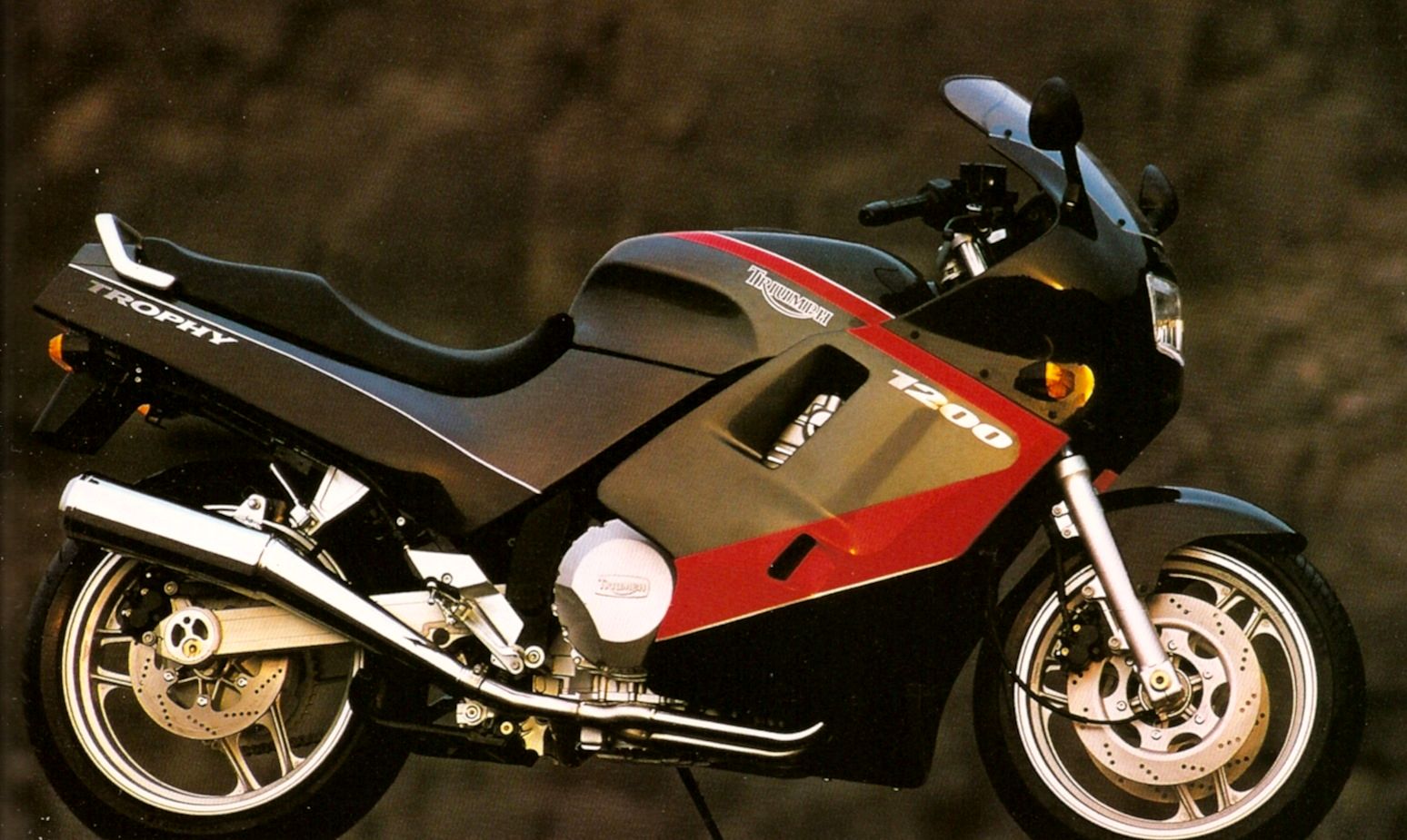
When the Trophy 1200 hit the roads in 1991, it was a surprise to just about everybody. Part of the surprise was left over from the astonishment of the Cologne Motorcycle Show in September 1990, six months earlier. 

Pre-production Trophy 1200 as Exhibited at the
Septermber 1990 Cologne Motorcycle Show

The paint and graphics for all models were revised following comments from show visitors and potential customers to the form they would retain until 1993. 


Journalists struggled to believe it wasn't just another myth or financial stitch up, that the motor would stay together without leaking oil, that there would be any engine-chassis combination that could work in a satisfactory way. There was a huge credibility gap for John Bloor and the likes of Bruno Tagliaferi and Gary MacDonald to fill.

The Daytona 1000 received a tepid response from the press at the time, though the passage of time allows a more sympathetic understanding of its virtues than the super-sports image permitted bay then. The Trophy 1200 amazed just about all the journalists who wrote about it for the urge available from its engine, positive and stable ride quality and general standard of finish.The Trophy 1200 filled the gap in a way that did proper service to all their careful planning, designing and development work. Inevitably, when looking back at journalists' statements about relative power twenty years ago, some read now as pure hyperbole couched in terms of the expectations of the day. Gazelles also may have moved differently in the early 1990s. However, the excitement and balance of the package are as clear now as they were then. 

Motorcycle News, March 1991:
"Since the engine is the most demanding piece of engineering in a motorcycle, the brilliance of the 1200 comes as the biggest shock. Power is everywhere ... at low rpm the sense of latent power is colossal, there's never any need to wait for the motor to gather is forces. ... The motor has more grunt than a charging rhino on speed but the chassis and tyres give the agility of a gazelle - an almost magical combination still rare even in todays' high-tech bike industry, and unheard of in connections with any british roadster."

Bike Magazine, May 1991:
"From 4000rpm, there's phenomenal, exhilarating urge that, thanks to the pari of gear-driven balance shafts in the sump, is honey-smooth up to 6000rpm, an id growls through its Motad stainless four-int-two pipes beyond that. A fearsome growl like no other. ... Taking the package as a whole, the plusses are massive and reek of well thought-out professionalism. ... It's not at the cutting edge of technology, there's no gimmicks, no upside-down forks and no fancy aerodynamics. But it is a damn fine bike powered by an astonishingly lusty, zestful engine."

Fast Bikes, June 1991
"Triumph motorcycle company have produced a bike that is not just good, it ... may be the best sports-tourer ever. [it has] a mighty furnace of free-flowing, unending power that pours forth with the continuity and inexorability of molten steel ... It hauls you to 100 on the merest tug of the throttle where the crank is spinning at a lowly six grand, yet it can pull away in top from the hundreds and fill its lungs as quickly over three figures as it does when you let the remarkably precise and glitch-free clutch out at a trickles. 'Torque-line' may be more appropriate than torque curve, as it just keeps on getting stronger all the way from 4000rpm to 8000rpm with no perceptible peaks or troughs. ... There is an almost perfect harmony of stance with the level of rake afforded by the screen an d fairing an d the Trophy is as capable of devouring peaceful, angst-free miles as any of the standards of sports-tourers."

A year or so later, the factory had gained confidence and was prepared to make bold statements about what it was about, where it had come from, and the values that would carry it forward. The Building on a Heritage video shows that Triumph still had a job to convince people they were for real. The format and accent of the narrator also shows how long ago it is now that this resurgence happened, underlining the historical significance of the relaunch in its own special way.


"The public at large could be excused for not appreciating that the current range of Triumph motorcycles was conceived, designed and manufactured in Britain. What also gets overlooked is the fact that it was the result of a decade of painstaking research design and development, building on a heritage."

Monday, October 10, 2011

Fuel tap rebuild

My fuel tap on my 1994 Daytona refused to turn off - petrol poured out regardless of tap position. The tap has three positions - on, off and prime. On and off are supposed to be controlled by a vacuum operated diaphragm that pulls a valve open when the engine is running. Prime holds the valve open via a cam in the tap so is the only position that should let fuel out of the tap with the engine off.

I managed to break the plastic knob when I was removing it. I had the 1991 Trophy one so could use it for the time being. The plastic knob engages with the aluminium fuel selector casting through a flat cast into its circular recess. This flat was the part that broke on the 1994 plastic knob. The 1991 one has the flat 90 degrees from the 1994 version, meaning the visible pointer on the outside of the plastic knob does not point down for reserve, back for on and up for prime. Instead, it points forward for  reserve, down for on and back for prime. 

Rebuild kit from Sprint Manufacturing
Extracting tap from tank
 I got a tap rebuild kit for £24 from Sprint Manufacturing.  It includes two new springs (one to hold the diaphragm closed when the engine is off, one to keep the selector valve in tension so it returns from the prime position), four new screws, a diaphragm, a rotary oil seal and two shaped rubber grommets to seal the tap body against the tank.


The body of the tap is held on to the tank with two long M6 screws that pass through the selector housing and fuel filter housing to engage with captive nuts.

Fuel systems don't like grit so it's important to have somewhere clean to do the job. I have an old set of stainless steel camping pans for jobs like this.

Vent hole (indicated byscrewdriver
tip)  to allow diaphragm
to pull valve out when the
engine is running. 

Removing diaphragm housing,
diaphragm valve closing spring
visible in the centre of the picture
The diaphragm is housed in a chamber at the rear of the tap. The cover is retained by four M4 Philips screws. It is likely to pop off under the pressure of the larger of the two springs in the tap body - get ready to catch it when it goes. 

There is a vent hole at the bottom of the diaphragm chamber, behind the fuel selector mechanism. I think my problem was probably dirt ingress through this vent hole interferring with seating of the diaphragm valve. 

Aluminium plunger with o-ring
under diaphragm
Diaphragm valve seat location
The diaphragm is actually two diaphragm components that attach to an aluminium plunger with an O-ring at one end. The two diaphragms fit either side of a plastic collar. There is a hole in the diaphragm that locates over the vent hole - a raised bump in the plastic collar helps to make sure it is round the right way on reassembly. 


After pulling the diaphragm housing apart, it was very clear that dirt certainly could have been responsible for the problem. So a thorough clean was required. 


There were traces of corrosion in evidence too so it carefully (there's a word) rubbed the sealing surfaces back with wet and dry on a foam sanding block.
Cleaned and ready for reassembly


I used silicon grease sparingly on the sealing surfaces, eased the new diaphragm into its plastic collar then, checking that the vent holes were aligned, installed the new spring and tightened down the M4 screws. 

New (left) and old (right) diaphragms
Installing new diaphragm, making
sure the vent hole is aligned to the
matching hole in the new diaphragm


With retaining screws released, the
fuel selector is pushed up by the small
screw on the prime operating rod
and can be lifted out. 

The fuel selector is made of two parts, one an aluminium casting and the other a plastic component that it turns inside the top body. The aluminium part is held into the tap body by two screws. These screws have plain ends that fit into a track that is cast into the ally selector - they twist off centre to force the tap in when turned to the prime position. This is actually what makes prime work because a long steel rod pushes through the centre of the tap onto the diaphragm valve when this happens, thereby pushing it open.

Fuel selector pushed into place and retained by screws.
The fuel selector positions are cast into tap body - these make
sense with the 1991 tap but don't match up for the 1994 tap

Friday, October 7, 2011

Cylinder head cover: from grotty to gleaming

As I wrote in my second blog post, the paint dear old Ruby's engine covers had not faired well from being left outdoors. The cylinder head cover in particular looked like it had the mechanical equivalent of a severe skin problem.


A previous owner had made an attempt to tidy it up a bit with silver spray paint from the timing side but without removing it or the fairing - hence the overspray on a fairing infill panel.

Well anyway, that makes for an interesting challenge, thought I. With all those grooves it's bound to be tricky stripping it clean. So off it came.


I wasn't wrong - it needed three treatments with paint stripper and some Scotch abrasive pads. These pads are a plastic alternative to wire wool. I have found wire wool clogs quickly and rusts in paint stripper. They worked well - it was easy to swill the painty gunge out under a tap and then to rub some more. After a good hose down, I cleaned up some pitting on the embossed Triumph logo with wet-and-dry abrasive paper on a  rubber sanding block.

 Another hose down and then time for paint. I used VHT silver in approximately five light coats (left picture), followed with a two light and then one heavy coat of VHT clear (right picture below).


VHT is heat curing. I knew it would be ages before the bike would be ready for me to run the engine so I *carefully* suspended the cover from a hook in my garage ceiling and then heated it up a bit at a time with a hot air gun. This is a tricky business to do - too hot too fast and the paint will fail and flake off. It all worked out well. I'm very pleased with the finish I have achieved, as hopefully the photos show.


These pictures were taken at different stages of the other work I've been doing with the rest of the bike, especially to do with the swinging arm and rear suspension.

Sunday, October 2, 2011

T300 CEV indicators

There's not too much to say about these indicators, other than that they are pretty well made by the CEV company. I had six all together: four from my Daytona and two from the Trophy. The Trophy had two odd replacements of unknown origin on the back. 

The indicators don't look sided at first glance but they are. There is small rectangular hole at the lower leading edge to allow water to drain out - if it gets in. All were pretty dirty inside so were treated to a nice warm bath. 


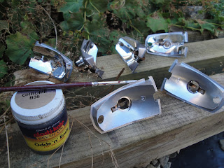
All were in reasonably good condition except one, which had a big crack down the side and showed lots of evidence of corrosion on the fasteners and also the flash-chromed reflector had crazed. Most had lost chroming around the edge where the amber lens bears down on them.

 I decided to use some Plastikote silver enamel paint (called 'chrome' but is more of a shiny silver) to seal the edges of all the reflectors, mainly to prevent the real chrome from being eroded further. I also painted the main surface of the reflectors that had suffered the most.
 I also coated the bulbs with an amber lacquer intended for fog lights, just because I'd had it for ages and thought, well, why not?